Solder Paste Inspection
"See the Unseen. Perfect Paste, Perfect Process."
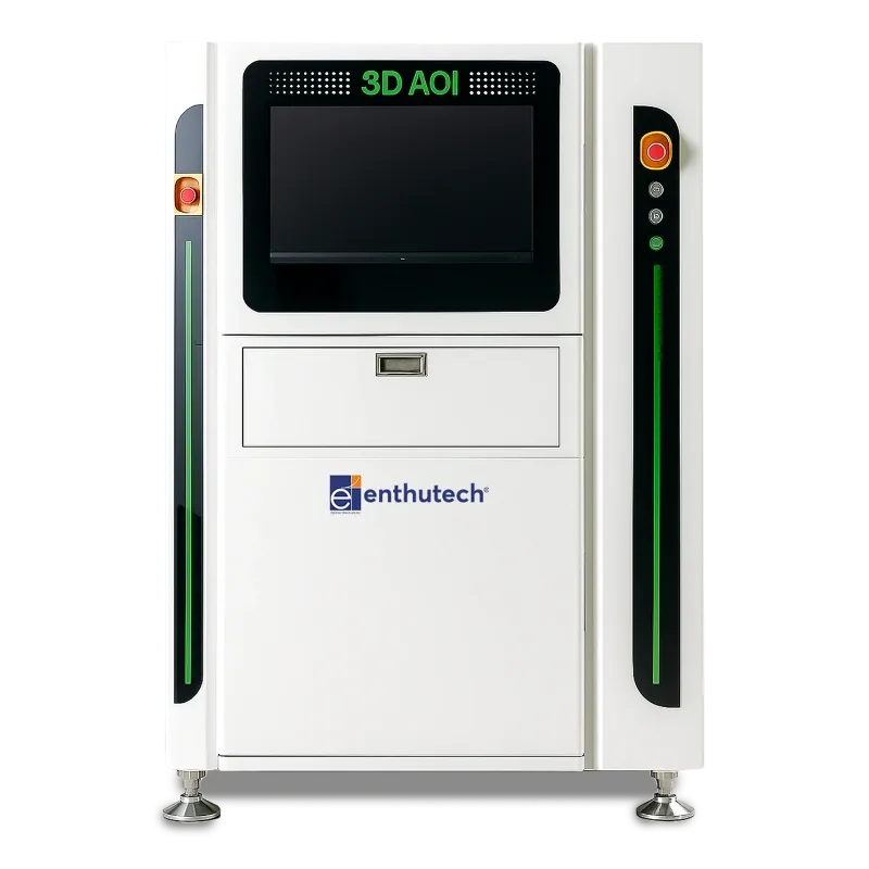
ETS - 3D SPI
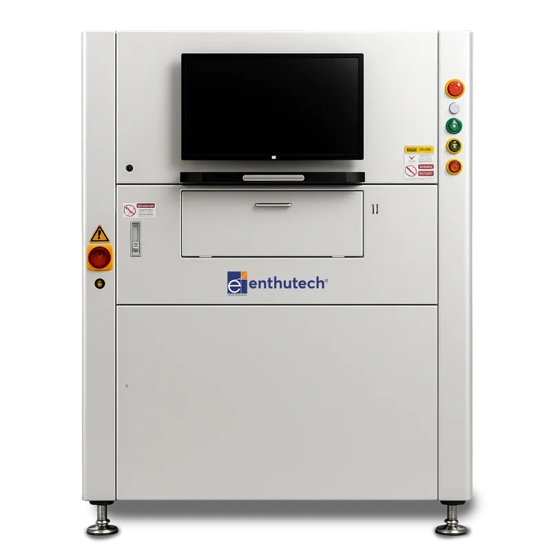
ETS - 3D SPI
Overview
The 3D Solder Paste Inspection (SPI) Machine from Enthu SMT Solution is an advanced inline inspection system designed to ensure accurate and stable solder paste quality before component placement. Using high-speed 3D optical measurement technology, the system precisely analyzes paste height, area, volume, shape, and displacement—providing complete process visibility for every PCB. Equipped with structured light projection and high-resolution cameras, the SPI machine generates true 3D profiles of each solder pad, enabling early detection of defects such as insufficient paste, excessive paste, bridging, smearing, misalignment, offsets, and stencil printing inconsistencies. Its intelligent algorithm automatically identifies and classifies defects, helping production teams correct printer parameters in real time.
- 5 MP camera with surrounding RGB lighting for clear 2D/3D true-color inspection.
- <0.7 seconds per screen for high-speed SMT production lines.
- 1 μm height accuracy with <1 μm repeatability for stable, reliable measurement.
- Supports paste sizes from 0.2 mm × 0.2 mm to 12 mm × 12 mm.
- Servo-driven X/Y system with <1 μm positional accuracy and 1500 mm/s PCB transport.
- Automatic width adjustment, edge-lock clamping, and support for PCB sizes from 50 mm × 50 mm to 500 mm × 460 mm.
- 3D grating projection head (optional dual head) for accurate area, volume, height, shape, and offset evaluation.
| Category | Specification |
|---|---|
| Camera | : 5 Mega Pixels |
| Lighting System | : Surrounding RGB Light Source |
| Field of View (FOV) | : 48mm × 40mm (20 μm) |
| Processing Time per Screen | : <0.7s |
| Inspecting Content | : Area, volume, height, shape, offset |
| Defect Detection | : Existence, more tin, less tin, continuous tin, offset, tip, collapse, irregular shape, insufficient height, height exceeding |
| Max. Inspecting Range | : 400 μm |
| Solder Paste Size Range | : 0.2mm × 0.2mm to 12mm × 12mm |
| Height Precision | : 1 μm |
| Repeatability (Size/Area/Height) | : <1 μm @ 3 sigma |
| R&R (Repeatability & Reproducibility) | : <10% |
| Operating System | : Windows 7 Ultimate 64-bit |
| Feature / Identification | : 3D grating projection head (double head optional) |
| Operation | : Graphical programming, Chinese/English switchable |
| Display | : 2D/3D True Colour Image |
| Mark Setting | : Supports 2 commonly used mark points |
| Programming Support | : Gerber, CAD import, offline programming, manual programming |
| SPC Support | : Any time period report, Histogram/Control Chart (volume, area, height, offset) |
| Export File Formats | : Excel (Report), JPG/BMP (Images) |
| PCB Delivery Method | : Edge-locked clamping, automatic access board, automatic width adjustment, in-line height 900±30mm |
| Min. PCB Size | : 50mm × 50mm |
| Max. PCB Size | : 500mm × 460mm |
| PCB Thickness | : 0.6mm–6mm |
| Board Edge Gap | : Top: 3mm, Bottom: 3mm |
| Delivery Speed | : 1500 mm/s (MAX) |
| Board Bending Compensation | : <2 mm |
| Driven Motor | : Servo Motor System |
| X/Y Platform Position Precision | : <1 μm |
| Moving Speed | : 600 mm/s |
| Computer System | : Industrial control computer with Intel high-end six-core CPU, 16GB DDR memory, 1TB hard disk |
| Monitor | : 22-inch LCD widescreen monitor |
| External Dimensions | : L(1090mm) × W(1290mm) × H(1534mm) without tri-colour lights, monitor & keyboard |
| Weight | : About 750 KG |
| Power Requirements | : AC 220V ±10%, 50/60Hz, 15A |
| Air Consumption Requirements | : 4–6 kg/cm² |
| Operating Temperature | : 10–40°C |
| Relative Humidity | : 30–80% RH |